Flex, not rigid: why the production board has to bend
A rigid board is the easy choice on the bench. Patch’s production circuit is a thin flexible one, and deciding that early changed more of the design than we expected.
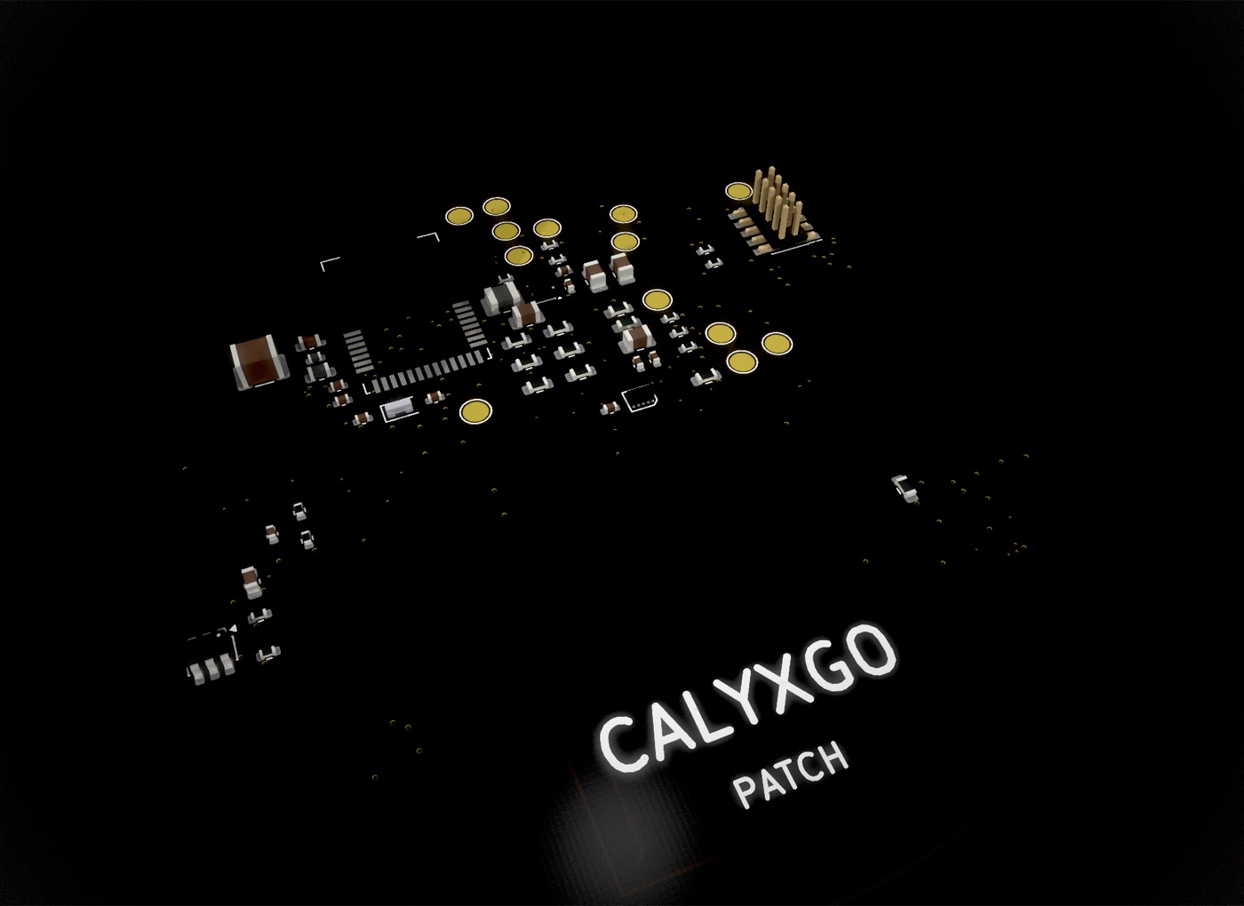
The board we develop on is rigid. Rigid boards are quick to order, easy to probe on the bench, and easy to change between revisions. For something that lives on an arm for weeks at a time, though, a rigid board was never going to be the final answer. The production board is a thin flexible circuit, and we decided that early. It changed more of the design than we expected.
Why it has to bend
An arm isn’t flat, and it doesn’t stay still. The inner upper arm curves in two directions and changes shape every time the muscle underneath moves. A rigid board can only touch a curved surface at a few points, and its edges want to lift. For a sensor that depends on steady skin contact, that is a problem twice over: anything that lifts the optics changes the reading, and anything that peels an edge shortens how long the patch stays on.
A thin flexible circuit can follow the curve, stay in contact across its whole face, and move with the arm instead of fighting it. It is also a large part of how the patch stays thin and light. A flexible circuit is a fraction of the thickness of a rigid board, and the adhesive and the shell can be built around it without adding bulk. The Patch page describes something that conforms to you and disappears into your day. Whether that happens is decided by the board.
What it changed
The board stopped being one uniform surface. On a rigid board every square millimeter is the same, and a part can go anywhere. On a flex, the places that bend and the places that carry parts have to be kept apart. Components and their solder joints don’t bend, so the areas under them have to be stiffened, and the areas between them have to be free of anything that would crack when the circuit flexes. The layout became a map of stiff islands joined by flexible bridges, and which parts share an island became a design decision rather than an afterthought.
Copper routes differently. Traces that cross a bending region have to be drawn to survive being bent again and again: smooth curves rather than sharp corners, no sudden changes in width, nothing that gives a crack a place to start. Connections that would have gone anywhere on a rigid board now have to pick their way across the flexible bridges, which makes routing harder and puts a hard limit on how many can cross from one island to the next.
The outline became part of the circuit. On a rigid board the outline is mostly a frame. On a flex, the outline decides where the circuit can bend and where it can’t, where the stiff regions are, and where the strain goes when the arm moves. The shape of the patch, the body and its three legs, was drawn together with the circuit rather than around it.
Testing had to be designed in. A rigid development board can carry a connector and test points wherever there is room. The production flex has no room to spare, so anything we need to reach on the bench has to be put there deliberately, and in a way that doesn’t carry over into the finished patch.
Every later decision got harder to change. On a rigid board, moving a part is cheap. On a flex, moving a part can mean moving a stiff region, which moves a bend, which moves the strain, which can change the outline. The design stopped being a set of independent choices and became one object, where pulling on any part of it pulls on the rest.